25+ schematic diagram of computer connected to a network
Where possible the arterial mains should be laid in duplicate. Pipe network analysis with examples.

Tda7294 Based Power Amplifier Circuit Design
The network diagram is a schematic depicting the nodes and connections amongst nodes in a computer network or more generally any telecommunications network.
. For further detail kindly check topmost 10 communication protocols used in PLC. The R3 is a pull-up resistor that is connected between Vcc and PB3 pins of IC while the Zener Diodes D1-D2 are added for total USB interface protection. Single-line Diagram Electrical Symbols.
It is the basic storage element in sequential logicFlip-flops and latches are fundamental building blocks of digital. Quickly browse through hundreds of Diagram tools and systems and narrow down your top choices. There are circumstances when the intricate conductor-by-conductor detail of a schematic is necessary but for quick analysis of operations and faults in large systems it is hard to compete with the elegance of a single-line diagram.
In electronics a flip-flop or latch is a circuit that has two stable states and can be used to store state information a bistable multivibratorThe circuit can be made to change state by signals applied to one or more control inputs and will have one or two outputs. B 22 Jun 2017. AutoCAD Electrical training courses and training material.
Filter by popular features pricing options number of users and read reviews from real users and find a tool that fits your needs. The AM335x microprocessor contains the subsystems shown in the Functional Block Diagram and a brief description of each follows. You need PLC programming instructions and programming to live the communication between different circuits of the PLC.
3 is a diagram of an SSB transmission scheme not being part of the invention. Above is a simplified version of the diagram. The server and Windows 10 computer 1 see each other and communicate easily without problems.
The communication protocols are useful for exchanging the information or data between connected devices through a network. Experienced with DIN IEC AS and US. Electrical Computer-Aided Design Consulting for AutoCAD AutoCAD Electrical 2017 ToolboxWD VIAWD and Promis-e.
1 is a diagram of a wireless communication system according to an embodiment of the disclosure. If you want to see a more detailed block diagram of VNA take a look at for example PNA-X Service Manual N5242-90001. B 27 Feb 2020.
But it can communicate with another program on your computer that can exchange data with the serialport. Need a schematic Car wiring diagram Service manual for a SaaB 2004 93 20 t Thank You Daniel Yelda email. Thank you very much its been difficult to find the correct schematic diagram again thank you 220.
Network diagrams are often drawn with professional drawing software tools. With the serial. On page 119 there is a very detailed block diagram of the RF parts.
Or feeders are pipelines of larger size that are connected to the transmission lines that supply the water for distributionA major water demand areas in a city should be served by a feeder loop. Schematic view of a potentiometer connected to analog in 0 of the Arduino. Powering the AM335x AM437x and AM438x with TPS65218D0 Rev.
The schematic is taken from the Digispark ATtiny85 board schematic but as we aim to build a programmer for ATtiny85 we are only connecting Male USB Plug with ATtiny85. Source is implemented using a phase locked loop and often frequency multipliers are used to reach the higher. Ed Bro Friday 29 January 2021 0549.
Thus if a firm say a computer manufacturer is utilizing the most up-to-date technology and if this technology is modified from say transistors to silicon chips then the production process and the. I checked the windows credentials and dont see an issue here. We would like to show you a description here but the site wont allow us.
There are different types of network diagrams provided by EdrawMax and you can get started with it now. The human immune system is composed of a distributed network of cells circulating throughout the body which must dynamically form physical associations and communicate using interactions between. 131 is a simple schematic presentation of the production process which can be conceived of as transforming inputs into outputs.
2 is a flowchart of a method for wireless communication according to an embodiment of the disclosure. Find and compare top Diagram software on Capterra with our free and interactive tool. I have each hard wired into a netgear switch.
Connected sensors in industrial automation Rev. Here is a set of some of the most commonly-used single-line diagram symbols. Eric colson Saturday 20 November 2021 0619.
For example a 10 ohm resistor connected in parallel with a 5 ohm resistor and a 15 ohm resistor produces 1 110 15 115 ohms of resistance or 30 11 2727 ohms. Industrial controls design specialists including schematic wiring diagram bill-of-materials wire fromto list and panel layout since 1988. A resistor network that is a combination of parallel and series connections can be broken up into smaller parts that are either one or the other.
4 is a diagram of an SSB transmission scheme not being part of the. 2nd Iteration 25 13423-192 13231. Im looking the complete engine wiring diagram schematic thats color coded for my 4dr 1994 honda civic sedan has a D15b7 engine in it for now but someone cut up a few wires in diffrent areas.
I connected Windows 10 computer 2 to the same switch but cannot connect to each of the other 2 units Windows 10-1 and server 2012. P5serialcontrol is the app that connects your sketch running in a browser with the serial ports on your computer as shown in Figure 10.
What Is The Difference Between A Schematic Diagram And A Pcb Layout Quora
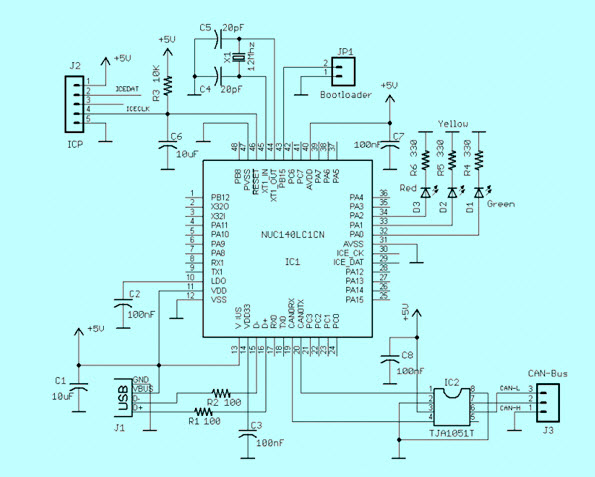
Can Interface To Usb With Schematic Diagram

Perhaps The Best 124 Light Emitting Diode Circuit Diagram Homeicon Info

Asus Rt Ac87u Rt Ac87r The Best 802 11ac Router Edge Up

Perhaps The Best 124 Light Emitting Diode Circuit Diagram Homeicon Info
What Is The Difference Between A Schematic Diagram And A Pcb Layout Quora
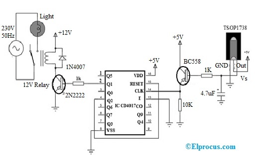
Remote Control Light Switch Circuit Working Its Applications
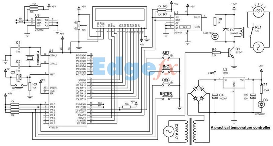
Temperature Controller Basics Circuit Operation And Best Application

Perhaps The Best 124 Light Emitting Diode Circuit Diagram Homeicon Info
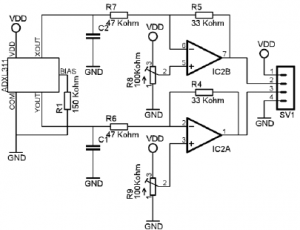
What Are Different Types Of Sensors With Circuits

Security Camera Wiring Color Code Free Download Diy Security Camera Security Camera Security Cameras For Home

Perhaps The Best 124 Light Emitting Diode Circuit Diagram Homeicon Info

Perhaps The Best 124 Light Emitting Diode Circuit Diagram Homeicon Info

Industrial Networking Wireless Topology You Ve Got Choices

Transmitter Receiver An Overview Sciencedirect Topics

Fuzzy Logic Enhanced Control For A Single Stage Grid Tied Photovoltaic System With Shunt Active Filtering Capability Ayachi Amor 2021 International Transactions On Electrical Energy Systems Wiley Online Library
Perhaps The Best 124 Light Emitting Diode Circuit Diagram Homeicon Info